
Plan the complete monitoring system.
A sensor is one part of the installation. These three examples identify the mounting, power and interface decisions to include in a configured quote. They are conceptual planning aids, not approved construction drawings or a bill of materials for ordering.
Request engineering documents →
Wet-tap at a powered site
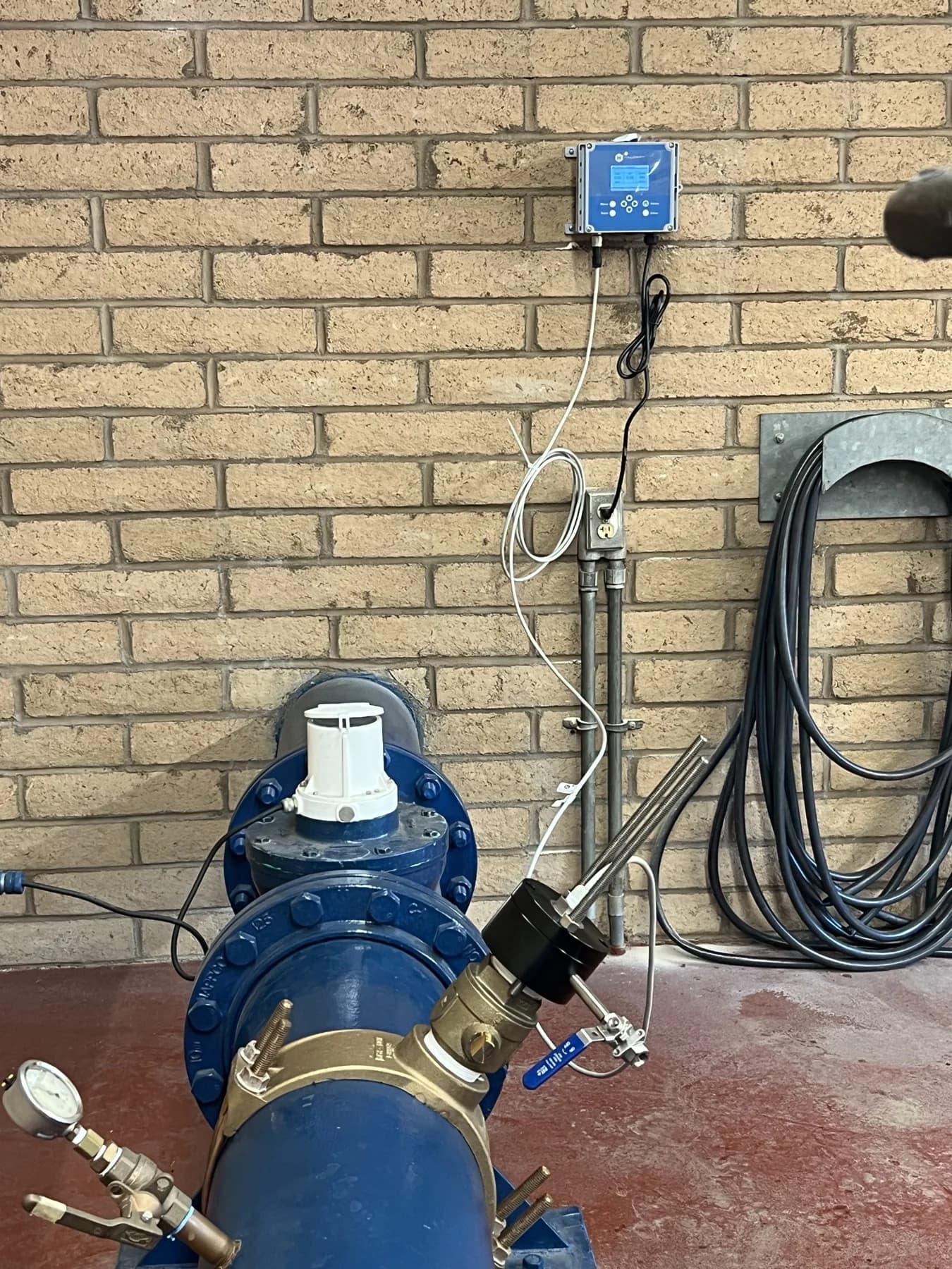
- Water main
- Approved wet-tap assembly + sensor
- D20 controller
- Configured PLC / SCADA input
Component checklist
- Sensor selected for the residual species and range
- Approved wet-tap assembly, corporation stop and removal hardware
- D20 controller and specified power supply
- Model-compatible cable and approved signal/interface hardware
Confirm before ordering
- Pressure, pipe size, material and assembly rating
- Site access and the approved installation procedure
- Power supply, cable run, signal scaling and controller configuration
Remote battery monitoring
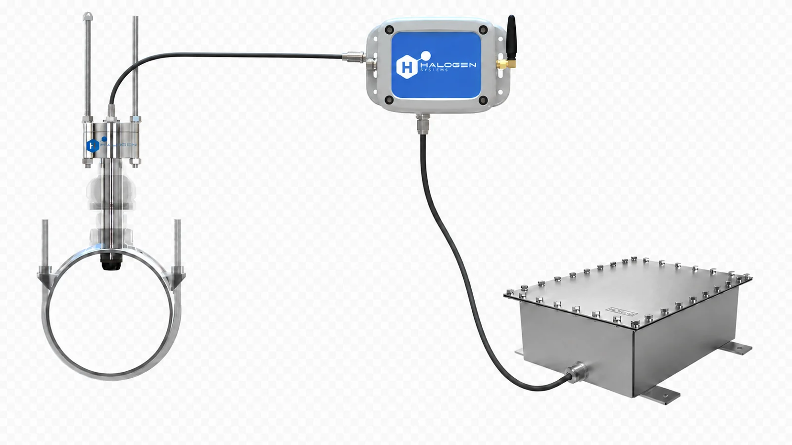
- Monitoring point
- Qualified low-power sensor
- Battery + BTSB interface
- Approved cellular / AMI / gateway path
Component checklist
- Qualified low-power sensor and mounting assembly
- BTSB variant matched to the communication path
- Sized battery, enclosure and approved power connections
- Antenna/gateway and configured service where required
Confirm before ordering
- Usable capacity, temperature, measurement duty cycle and reporting interval
- Cellular/AMI availability and loss-of-signal response
- Service reserve, reference checks and battery-replacement access
Tank or clearwell immersion
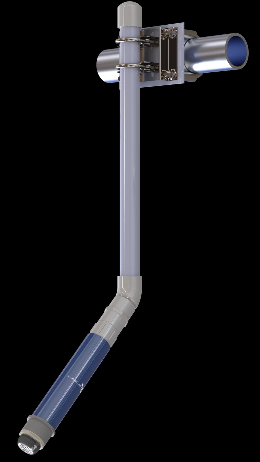
- Representative tank location
- Qualified immersion sensor + mount
- Cable to controller / interface
- Operator display or monitoring system
Component checklist
- Sensor and immersion configuration selected for the water
- Approved bracket, support and cable arrangement
- D20 for a powered site or separately qualified low-power interface
- Power and communication equipment for the selected configuration
Confirm before ordering
- Approved depth, wetted materials and temperature
- Representative location, air avoidance and retrieval access
- Cable protection, controller location and verification sample point
Connections are configuration-specific.
Do not infer terminal assignments or register addresses from these diagrams. Use the manual for the controller, firmware and sensor generation. The D20 is not the default controller for a battery-operated site.
Current and historical manuals → · 4–20 mA, Modbus and IoT guide →
Request engineering documents.
Tell us the sensor model, controller, firmware if known, mounting arrangement and required interface. Halogen Systems will help identify the appropriate drawings, wiring information, register maps and component list for your project.
Technical information is provided by Halogen Systems. Project-specific documents are supplied following configuration review.