ENGINEERED FOR WATER. BUILT FOR THE FIELD.
My Halogen Track an order Cloud login
Halogen Systems
HALOGEN SYSTEMS · MARINE TRO

TRO sensors for ships, seawater and ballast water.

Find the measurement behind your marine treatment system. Halogen helps shipowners, engineers and service teams measure total residual oxidant in seawater, select a marine sensor and identify an installed unit.

Shipowners · Fleet technical teams · Marine service partners · BWMS OEM manufacturers

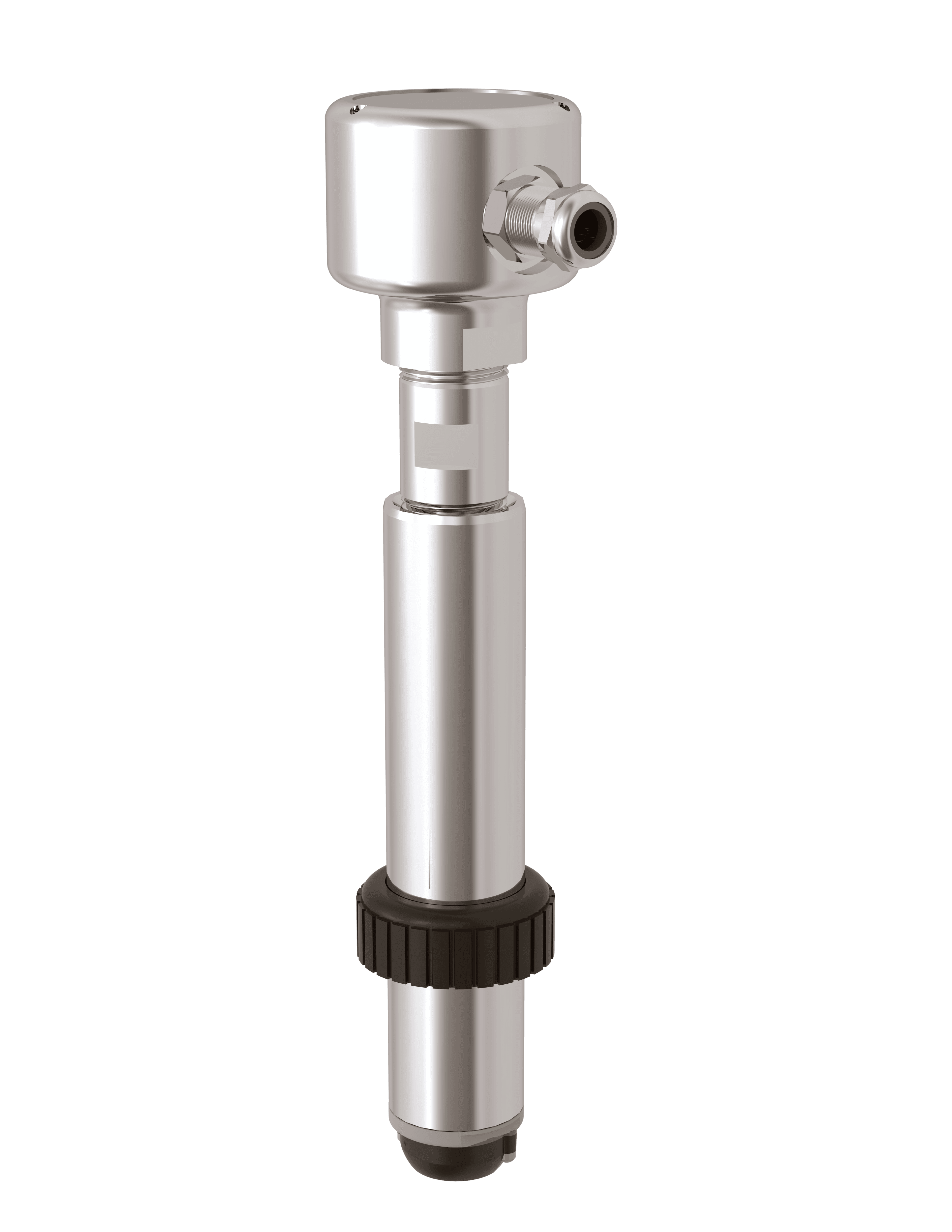
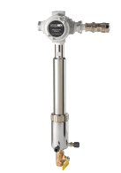
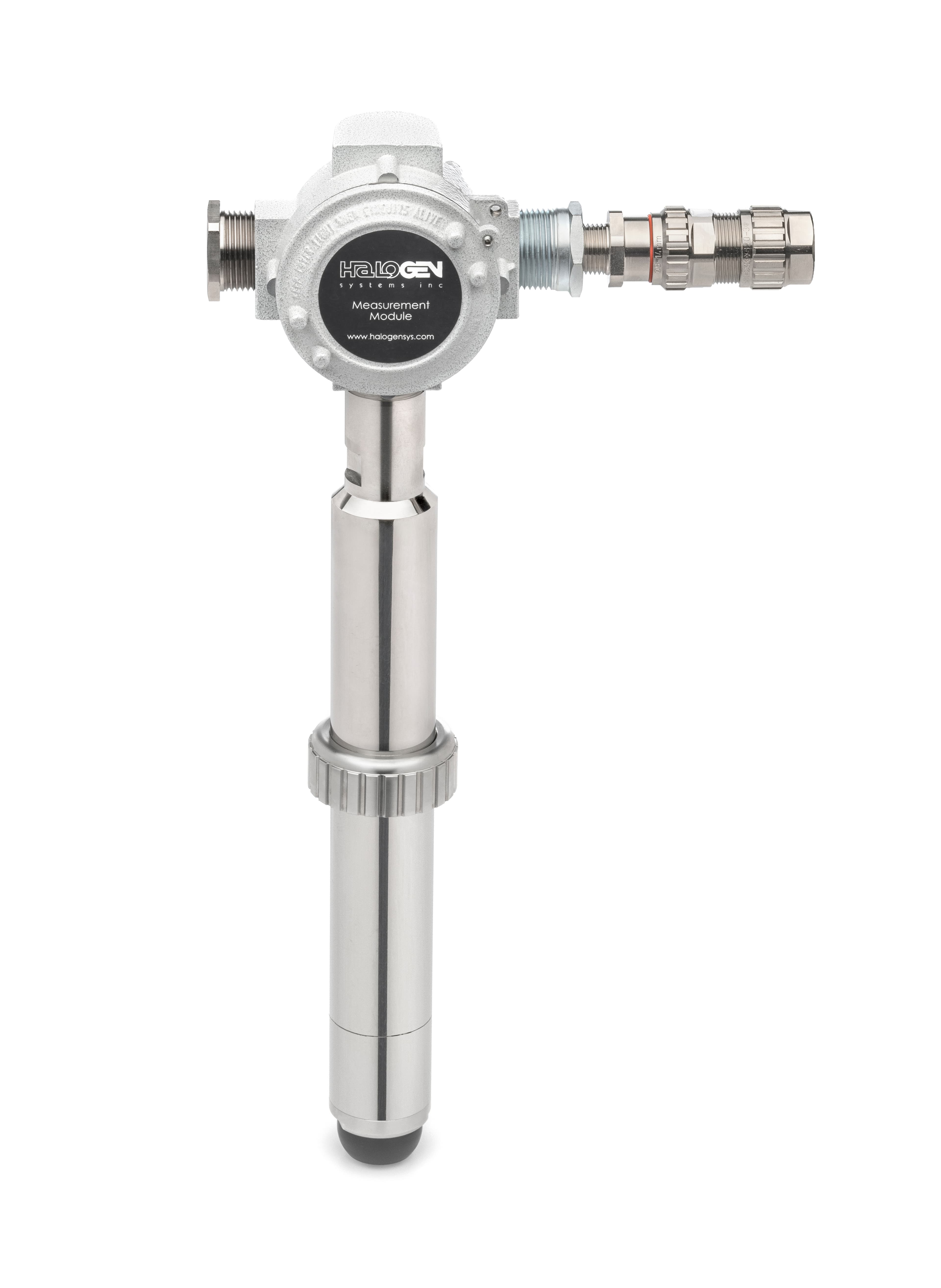
Halogen TRO measurement module, EX housing and long insertion probe, front view
Halogen TRO measurement module · EX configuration shown

4,500+ TRO sensors delivered for ballast water management systems worldwide.

DNV-GL · Korean Register (KR) · IECEx
Marine approvals are configuration-specific. Request the applicable certificates for your selected model.

Halogen Systems has manufactured sensors since 2013 near Reno, Nevada, with more than eleven patents worldwide. Explore the patents ↗

FEATURED IN RIVIERA MARITIME MEDIA

Marine engineering experience, in the industry press.

Riviera’s February 2021 feature reports on DNV GL type approval for Halogen’s direct-insertion TRO sensor and shares feedback from ballast water treatment engineers on installation simplicity, reliability and reagent-free operation.

“BWMS designers should look closely at the Halogen TRO sensor.”

Cheon-Il Kang, Director (TOMA), Shin Woo E&T Co Ltd, quoted in Riviera
Read Riviera: Low maintenance, lower-cost TRO sensor receives DNV GL type-approval ↗

Riviera Expert Views · · Sponsored by Halogen Systems Inc. Refer to the applicable current certificate for your sensor configuration.

Aerial view of a container ship at sea with the Halogen Systems logo
FEWER SUPPLIES. A SHORTER SAMPLE PATH.

At sea, simpler TRO monitoring matters.

Reagent-free measurement takes one recurring supply requirement off the voyage plan. Direct pipe insertion takes the sample line out of the measurement path.

No reagent delivery to wait for.

When a vessel is underway, replacing analyzer chemicals is not a quick trip to a supplier. Crews must plan inventory, storage and replenishment around voyages and port calls. Halogen’s TRO measurement needs no analytical reagents to stock, prepare or replace.

Measure before the sample changes.

Biofilm and deposits in sampling tubing can consume residual oxidant on its way to an analyzer. The delivered sample may no longer represent the water in the ballast pipe. Measuring directly in the pipe avoids this external sample-line loss and transport delay.

Less plumbing for the crew to maintain.

Direct insertion removes the separate sample tubing, sample pump and analyzer drain from the installation. Reagent-free sensing also removes reagent-feed tubing and its associated blockage checks. The crew can focus on the sensor and its measurement point.

Compare the complete measurement installation
Operator considerationReagent-based analyzer with a sample lineHalogen direct pipe insertion
Voyage suppliesPlan reagent stock, storage and replacement.No analytical reagent inventory.
Sample integrityMaintain tubing cleanliness and account for transport time.Measures at the pipe; no external sample-line journey.
Service pointsMaintain reagent delivery and sample-handling components.No reagent-feed system or external sampling circuit.

Comparison applies to Halogen direct-insertion installations; side-stream installations still require sample-path care. Reagent-free measurement does not eliminate BWMS treatment chemicals or routine sensor service. Read Halogen’s technical discussion of direct measurement and sample-line delay ↗

Review my TRO installation
FOLLOW THE WATER

Know what the residual reading needs to tell you.

01 / Ballasting

Is treatment delivering the intended residual?

In a full-flow electrochlorination system, locate the treatment measurement after electrolysis and adequate mixing. The TRO signal helps the control system follow oxidant production as ballast water enters the tanks.

02 / De-ballasting

How much residual remains?

Measure the water leaving the ballast tanks to inform neutralizing-agent dosing. Give the crew a clear view of the residual and the measurement status during discharge operations.

03 / Final discharge

Has neutralization achieved the target?

Check the residual after neutralization at the designated final monitoring point. Match the low-range performance and alarm settings to the approved system requirements.

ENGINEERED FOR MARINE DUTY

A robust solution starts at the sensing surface.

Less sampling equipment

Direct Pipe Insertion measures in the ballast line without a separate sample pump, sample tubing or analyzer waste line. Reagent-free and membrane-free TRO measurement means no analytical reagents to replenish.

Active electrode cleaning

SensiCLENE circulates polymer beads around the electrodes to remove salt and organic deposits. HiRes TRO maintains local flow at the sensing surfaces as pipe flow changes.

Changing water. Empty pipes.

HaloSAL compensates using conductivity. DryGLAS pH and Rapid Response ORP technology address the dry periods that occur when ballast piping is emptied.

HiRes TRO™

An impeller drives flow across the electrodes for direct pipe measurement as ballast-line flow changes from 0 to 4 m/s. The magnetically coupled pump motor has a published 20,000-hour life expectancy.

SensiCLENE™

Circulating polymer beads continuously clean the electrodes. Salt and organic buildup are removed within minutes of startup. The marine design needs no sensor filters to clean and is designed for turbid water in muddy ports.

DryGLAS™

The pH cartridge tolerates dry-out and the positive and negative pressures encountered in ballast piping. It stabilizes within minutes after extended dry periods.

HaloSAL™

Conductivity-based automatic salinity compensation supports measurement from seawater to freshwater at 0.2 PSU salinity.

Rapid Response ORP™

For systems using ORP, the sensor is designed to survive dry periods without dry-out damage or poisoning.

HSI vs. DPD — published cost and labor comparison
Maintenance considerationHalogen DPIDPD reference in the brochure
Calibration / service interval6–12 months1 month
Time to measurement at PLC45 seconds180 seconds
Maintenance interval24 months1 month
Very turbid waterListed as unaffectedListed as affected

Historical comparison from the supplied May 2021 brochure, not a specification for every current DPD analyzer. The measurement cycle is separately specified as 45–55 seconds. Direct pipe insertion also avoids a separate analyzer skid, sampling-circuit automatic valves, pressure regulators and Y-strainers.

Seawater brings more than salt.

For crews working around fouled pipework, the practical questions are access, cleaning and dependable measurements after a restart. Discuss those conditions early, whether the monitoring point is on a ship, tanker or offshore installation.

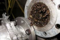
Marine fouling examples. These photographs show the application environment, not a sensor performance test or before-and-after treatment result.

Marine organisms accumulated inside seawater pipework
Pipework fouling
Marine fouling visible at an open pipe and valve connection
Fouling at a connection

Halogen publishes 6–12 months between calibration checks and a 24-month maintenance interval for this marine range. Plan service around the selected configuration and operating conditions. Marine technology details ↗

FOR BWMS OEM MANUFACTURERS

Direct in the pipe. Direct to your PLC.

Build TRO monitoring into your own system, with your own operator interface and branding. Halogen’s reagent-free TRO sensor can communicate directly with your PLC over Modbus RTU without a separate Halogen controller, with integration development for your application.

Your installation.

Install the sensor directly in the ballast pipe using the appropriate flange or hot-tap configuration. Measure at the process point without external sample tubing or a separate analyzer skid.

Your PLC.

Bring measurements into your control system through Modbus RTU. Develop the PLC interface for the selected sensor, including register mapping, measurement scaling, sensor status and fault handling.

Your brand.

Present TRO readings, trends and alarms through your own branded HMI. Keep the operator experience within your BWMS interface, and discuss OEM sensor labeling with Halogen as part of the integration review.

A flexible installation, with engineering built in. Direct PLC integration requires development and commissioning. Review the sensor’s electrical and communication requirements, implement your system’s control logic, and validate measurement and alarm behavior before putting the installation into service.

EXPLORE THE TRO SENSOR RANGE

Choose your mounting. Match your environment.

Compare all six configurations in the marine brochure, with non-hazardous and hazardous-area options for each installation type.

In-pipe / flange sensor — SWN-P+
Non-hazardous

In-pipe / flange sensor

SWN-P+

Direct insertion into ballast piping through the specified pipe or flange connection.

Ask about this model ↗
Side-stream sensor — SWN-P+CHM
Non-hazardous

Side-stream sensor

SWN-P+CHM

Sensor with a measurement chamber for installations using a representative side stream.

Ask about this model ↗
Hot-tap sensor assembly — SWN-P+HT2-HTV-01
Non-hazardous

Hot-tap sensor assembly

SWN-P+HT2-HTV-01

Direct-insertion sensor with the matching hot-tap valve assembly.

Ask about this model ↗
In-pipe / flange EX sensor — EX-P-STD2
Hazardous-area variant

In-pipe / flange EX sensor

EX-P-STD2

EX measurement module for the specified flange or pipe installation.

Ask about this model ↗
Side-stream EX sensor — EX-P-STD-CHM
Hazardous-area variant

Side-stream EX sensor

EX-P-STD-CHM

EX sensor with a side-stream chamber. Confirm sample supply and installation requirements.

Ask about this model ↗
Hot-tap EX sensor assembly — EX-P-HT4-HTV-1
Hazardous-area variant

Hot-tap EX sensor assembly

EX-P-HT4-HTV-1

EX sensor with a matching valve assembly for direct pipe insertion.

Ask about this model ↗

Images illustrate the sensor configurations. Confirm the complete ordering code, mounting dimensions and applicable certification with Halogen.

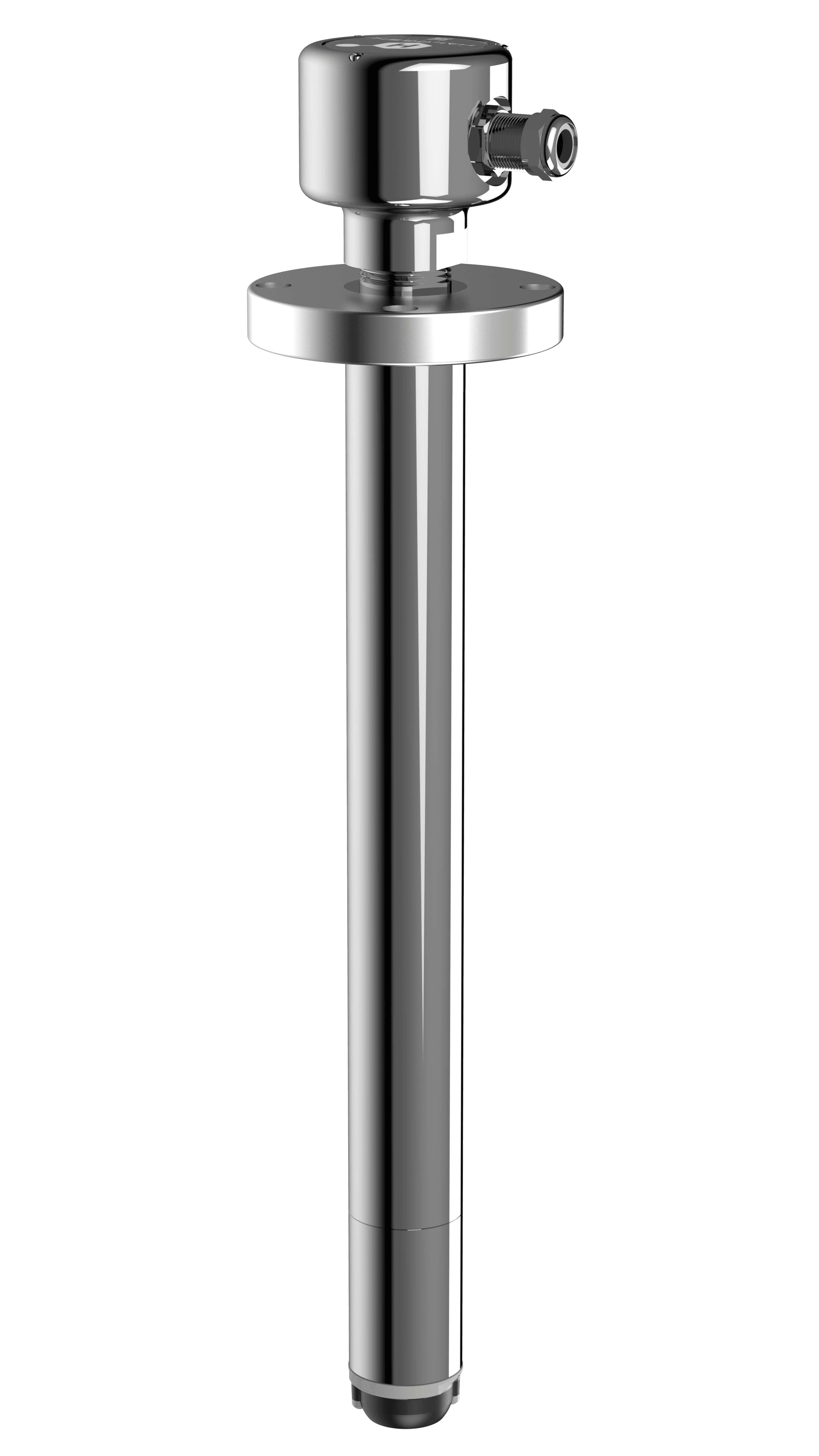
Halogen WT titanium sensor with flange and long insertion probe
TITANIUM SENSOR OPTION

WT titanium sensor

Shown with a flange-mounted long insertion probe. Share your pipe dimensions, insertion requirements and seawater duty so Halogen can confirm the correct titanium configuration and ordering code.

SPECIFY THE MARINE RANGE

TRO specifications and installation options.

Published measurement specifications

TRO measurement range0.03–20 ppm
TRO accuracy±15% or ±0.06 ppm, whichever is greater
ORP−1,100 to +1,100 mV
Conductivity / salinity channel200–50,000 µS (published units)
pH5–12
Temperature measurement0–100 °C
Measurement cycle45–55 seconds, depending on selected measurements
Digital communicationModbus RTU

Choose the installation

MountingNon-hazardousHazardous variant
Pipe / flangeSWN-P+EX-P-STD2
Side-stream chamberSWN-P+CHMEX-P-STD-CHM
Hot-tap assemblySWN-P+HT2-HTV-01EX-P-HT4-HTV-1

Published hazardous-area marking: Ex db ib IIC T5 Gb, Zone 1, Group IIC.

A separate Halogen controller is not required when the sensor is integrated into an OEM PLC with the necessary development. Optional non-hazardous D01 / D01-4 transmitters provide two / four 4–20 mA outputs, 24 VDC input and Modbus RTU.

Source: Halogen marine brochure, specification and model tables. Measurement ranges are not installation operating limits. Request the current model datasheet for pressure, wetted materials, temperature limits and certification scope. Confirm low-residual performance against your system’s discharge criterion.

How should I interpret the published chlorine detection limit?

The existing product page lists 0.03 ppm in its detection highlight and 0.0–0.25 ppm in the chlorine limit of detection (LOD) row. These are different statements. The measurement range shown here is 0.03–20 ppm; ask Halogen for the model-specific detection limit and low-residual validation before specifying a discharge-monitoring point.

Cover of the Halogen Simple, Reliable, Low Maintenance TRO Measurement brochure
BROCHURE · PDF · 8 PAGES · 7.5 MB

Take the marine TRO brochure with you.

Download the sensor model guide, measurement specifications, installation comparison and marine technology overview for your vessel or engineering team.

Brochure edition: May 2021. Contact Halogen for current configuration and ordering details.

SEE THE ASSEMBLY

WT titanium sensor removal animation.

Assembly animation · approximately 65 seconds. Use the applicable installation and service manual for removal procedures.

Download the removal video (MP4 · 5.6 MB) ↓
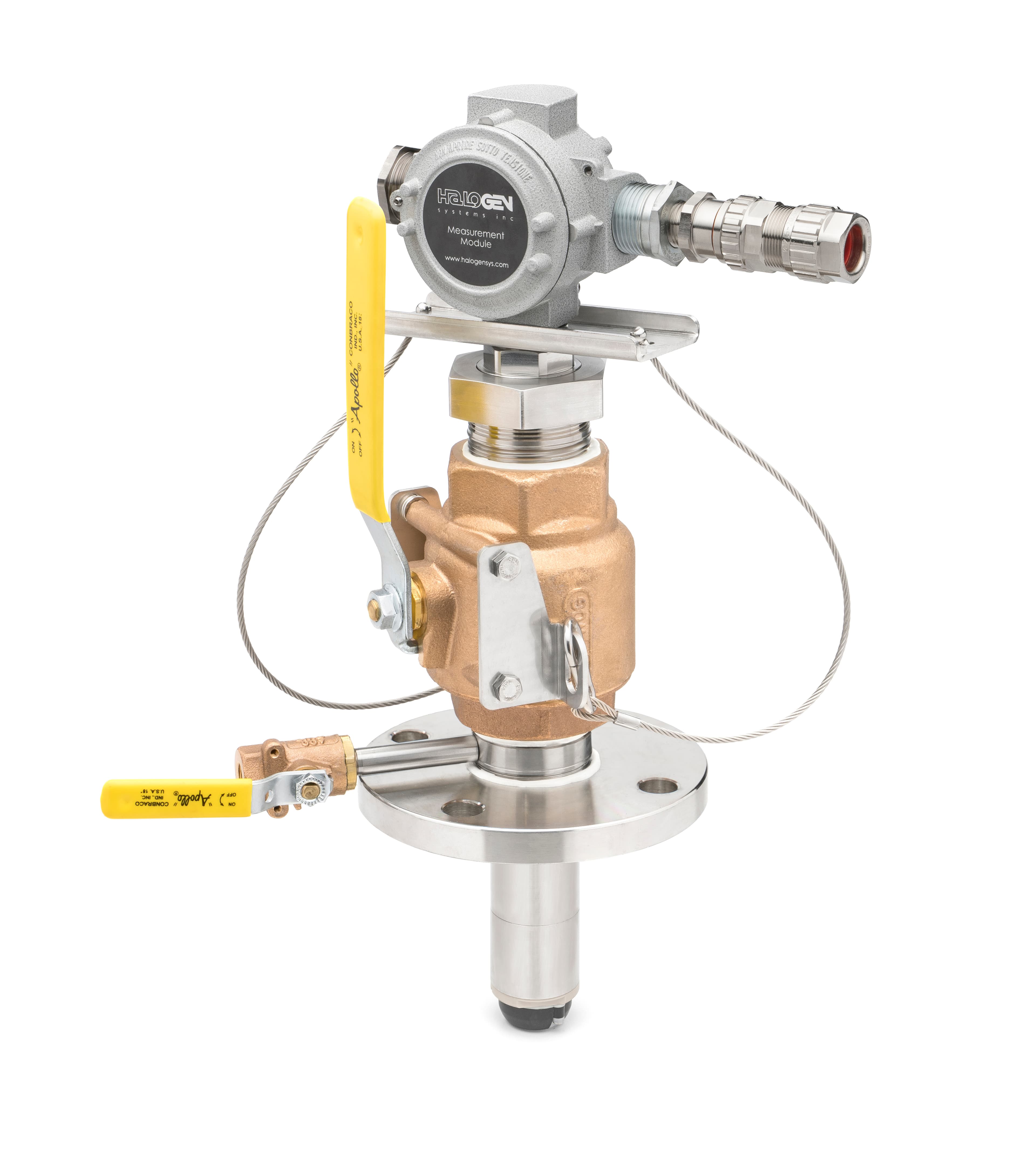
Halogen EX TRO sensor mounted in a valve assembly with yellow handles and retention cables
Valve-mounted sensor assembly · match the complete configuration
ALREADY INSTALLED ON YOUR VESSEL?

Recognize the sensor. Confirm the right part.

A TRO sensor supplied with your ballast water treatment system may carry the system supplier’s label. If the measurement module or probe looks familiar, Halogen can help identify it.

For a replacement sensor, spare probe or service enquiry, send:

  • Nameplate and serial-number photos
  • BWMS manufacturer, model and vessel name
  • Probe, connector and valve or flange photos
  • Existing part number and any displayed alarm

We’ll help match the sensor and mounting arrangement. Replacement selection also needs the system’s electrical, software and approval requirements.

Get help identifying my TRO sensor
ANSWERS FOR ENGINEERS & CREWS

Before you specify or replace a sensor.

Does a Halogen TRO sensor need a separate controller?

No. An OEM can integrate the TRO sensor directly into its PLC using Modbus RTU, without a separate Halogen controller. This requires PLC integration development and commissioning for the selected sensor configuration, including measurement mapping, status handling and system control logic. Direct pipe insertion and direct PLC communication give the OEM flexibility in both mounting and control-system design.

Can OEM manufacturers use their own branding and operator interface?

Yes. OEM manufacturers can present Halogen TRO measurements through their own PLC and branded HMI rather than a separate Halogen controller. The OEM develops the interface, alarms and control logic within its own system. Discuss sensor labeling and the required integration configuration with Halogen during the design review.

What is a TRO sensor in a ballast water management system?

A Total Residual Oxidant (TRO) sensor measures residual oxidant in treated ballast water. In an electrochlorination BWMS, that measurement supports treatment control, neutralization dosing and final discharge verification. Halogen provides reagent-free sensors for direct pipe insertion and side-stream installations.

What does the Halogen marine sensor measure?

The marine range reports chlorine (TRO), oxidation reduction potential (ORP), conductivity / salinity, temperature and pH where configured. The published TRO range is 0.03–20 ppm, with accuracy of ±15% or ±0.06 ppm, whichever is greater. Communication is Modbus RTU.

Why choose a reagent-free TRO sensor at sea?

Reagent-based monitoring adds chemicals to the vessel’s stores, with storage conditions, usable life and replacement schedules to manage. Halogen measures TRO without analytical reagents, removing that resupply dependency from the measurement. Treatment and neutralization chemicals remain separate requirements of the BWMS.

Can fouled sample tubing change a TRO reading?

Yes. Deposits and biofilm in a sample line can consume oxidant before the water reaches the analyzer, so the reading may understate the residual in the ballast pipe. Transport time also delays the reading. Direct pipe insertion removes that external sample-line path; the sensor still needs correct placement and routine verification.

How do I identify a privately labeled TRO sensor?

Your system documentation may call it a TRO monitor, residual oxidant sensor or measurement module. Halogen sensors can be supplied under a system supplier’s label. Send the nameplate, serial number, photos of the probe and mounting assembly, and the BWMS make and model. We can help establish the sensor identity and the correct service route.

Can I order a replacement from a photograph?

A photo starts the identification process. Before ordering, match the part number, insertion length, mounting, electrical interface, firmware requirements and area classification to the installed system. Similar housings do not establish interchangeability.

Where does a TRO sensor fit in an electrochlorination BWTS?

Typical monitoring duties include checking oxidant after electrolysis, measuring remaining residual during de-ballasting, and verifying neutralization before overboard discharge. Use the measurement points and acceptance criteria specified for your treatment system.

Can Halogen help with offshore seawater monitoring?

Yes. Share whether the duty is ballast treatment, a seawater intake or a cooling-water circuit, together with oxidant chemistry, expected residual and installation conditions. The team can review the appropriate sensor configuration for your vessel or facility.

Does TRO mean every oxidizer in seawater can be measured?

No. Define the oxidant chemistry and the reporting basis for your process. A chlorine-based seawater treatment duty should not be treated as evidence of suitability for every other oxidizer. Ask for a review of the actual treatment chemistry.

YOUR NEXT STEP

Bring us the measurement point—or the sensor you have.

Help me choose a sensor ↗