ENGINEERED FOR WATER. BUILT FOR THE FIELD.
My Halogen Track an order Cloud login
Halogen Systems

This guide covers earlier-generation MP5 / MP5A equipment. For new projects, explore the current MP-5F and Halogen Academy. Use the manual for your exact model and assembly.

Earlier-generation MP5 / MP5A application guide

MP5 / MP5A Low-Flow and Zero-Flow Installation Guide

Practical setup, stabilization, calibration, cleaning, and troubleshooting guidance for pipes, tanks, dead ends, and side-stream installations.

Technical author: Michael Silveri, Halogen Systems Inc. · Reviewed August 31, 2026 · Specifications: Halogen Master Specifications v19

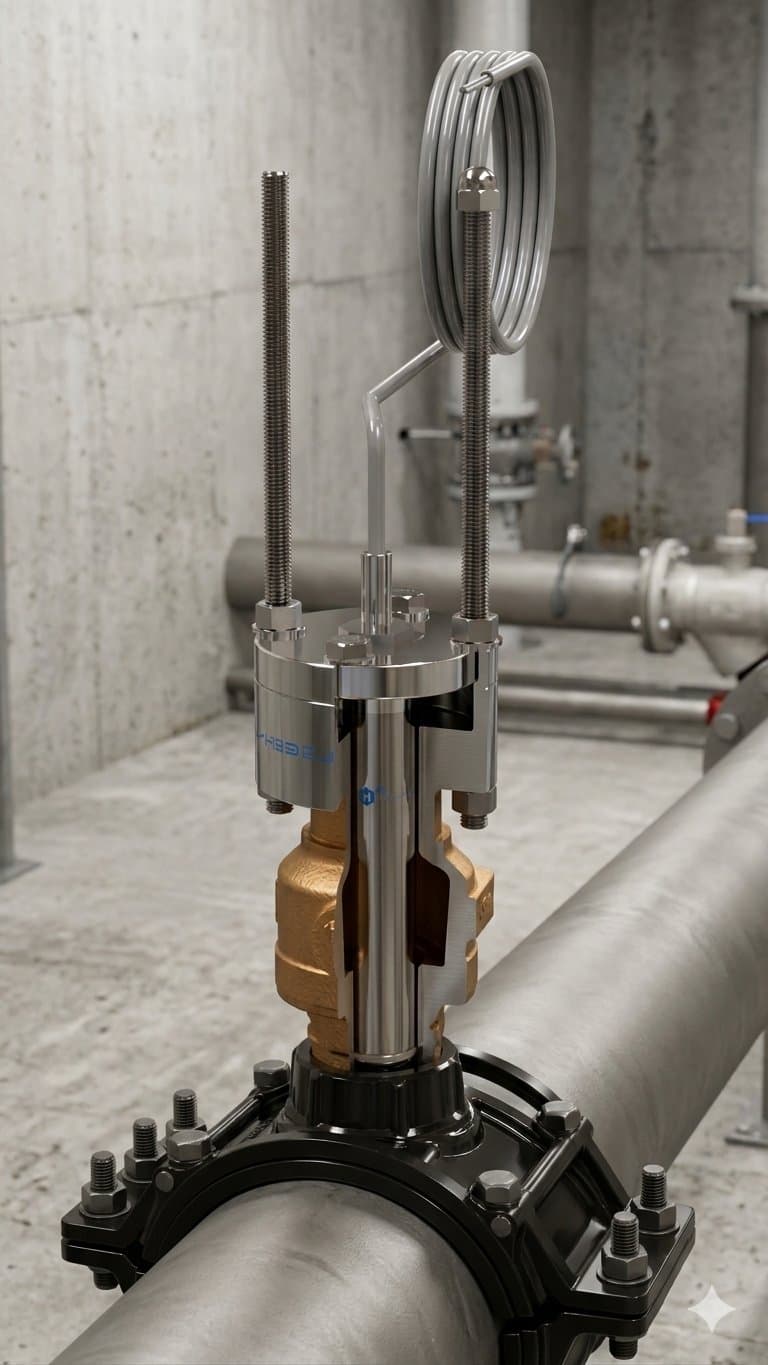
MP5A direct in-pipe wet-tap installation for low-flow chlorine monitoring

Quick Answer

How can chlorine be monitored accurately at low or zero flow?

For low-flow drinking-water locations, the MP5A uses an internal impeller to control water movement across its electrodes, so the chlorine measurement does not depend on pipeline velocity. Direct in-pipe and immersion installations can measure at zero external flow. Side-stream flow cells still need 0.1–1.0 L/min to stay full and representative.

Best for

  • ●Dead-end and intermittent-flow distribution mains
  • ●Storage tanks, clearwells, reservoirs, and open basins
  • ●Remote sites where reagent handling and waste drains are impractical
  • ●Process points with variable hydraulic conditions but representative water

Not best for

  • ●Locations with persistent air entrainment, cavitation, or severe turbulence
  • ●Points immediately downstream of chemical injection before mixing is complete
  • ●Side streams that cannot keep the cell full or deliver a fresh sample
  • ●Applications outside the approved chemistry, temperature, pressure, or material limits

Choose the installation before you set the flow

“Flow independent” refers to water movement at the sensing electrodes. It does not mean a long side-stream sample line can stop moving and still represent current process water.

InstallationExternal flowBest forWatch for
Wet-tap (direct in-pipe)0–4 m/sLive mains, dead ends, pressure zones, and locations without a sample drainAir entrainment, cavitation, poor mixing near chlorine injection, and representative placement
Immersion0–4 m/sTanks, clearwells, reservoirs, basins, and intermittent-flow locationsSecure placement, adequate submersion, bubbles, and stratification
PVC tee0–4 m/sPermanent direct-pipe installation when shutdown and pipe access are availableCorrect orientation, air pockets, and enough clearance for service
MKIT side-stream flow cell0.1–1.0 L/min through the flow cellWall-mounted in-plant or demonstration setups where a side stream is preferredVertical cell, outlet up, chamber kept full, inlet pressure ≤60 psi, and transport lag in long sample lines

Low-flow commissioning workflow

1

Select a representative point

Install after adequate chemical mixing and away from bubbles or cavitation.

2

Fill and purge

Keep the sensor submerged. For MKIT, mount vertically, outlet up, and purge all air.

3

Allow stabilization

Expect pH stabilization in about 5 minutes; run the full sensor at least 20 minutes before calibration.

4

Calibrate in order

Calibrate pH first, then chlorine using a representative, consistently timed DPD sample.

5

Verify the trend

Confirm stable readings, alarms, timestamps, and process response before relying on the point.

Common low-flow failure modes

Start with installation and sample quality before recalibrating. A bucket test is the fastest way to separate a sensor problem from an air, mixing, or plumbing problem.

SymptomLikely causeOperator response
Bouncing or erratic chlorineAir bubbles, cavitation, or a point too close to chlorine injectionRun a bucket test. If the reading stabilizes, correct the installation or relocate the measurement point.
Air-in-sensor errorDry sensor, trapped air, or a flow cell that is not staying fullRestore water, orient a flow cell vertically with the outlet up, purge air, then clear errors to start self-priming.
Stable reading but slow process responseLong or oversized side-stream tubing, very low delivery flow, or stale sample volumeShorten the sample path, use the specified 1/4-inch tubing, and confirm 0.1–1.0 L/min through the MKIT.
Calibration does not match a grab sampleInsufficient wetting time, inconsistent DPD timing, poor sample location, or pH not calibrated firstAllow at least 20 minutes in water before calibration, calibrate pH first, and use a representative, consistently timed DPD sample.
Flow cell looks dirty or tubing is discoloredDeposits, aged tubing, or biofilm in the sample pathReplace damaged or fouled tubing. Clean acrylic with detergent or diluted acid—never solvents.
videocam

Low-flow demonstration

Video production pending

Prepared video module

What the demonstration will show

  • • A real MKIT low-flow setup at 0.1–1.0 L/min
  • • Correct vertical orientation and air removal
  • • Stabilization and pH-first calibration
  • • Bubble, stale-sample, and poor-mixing failure modes
  • • Bucket test, cleaning, and return-to-service checks

Frequently asked questions

Will the MP5A measure chlorine at zero flow?

Yes, in direct in-pipe and immersion installations. The MP5A internal impeller creates controlled movement across the electrodes, so its measurement does not depend on pipeline velocity. Zero external flow does not eliminate the need for representative placement, adequate submersion, and freedom from trapped air or cavitation.

Does a low-flow MP5A flow cell need sample flow?

Yes. Flow independence describes the sensor measurement, not transport of water from the process to a side-stream cell. The MKIT flow cell should receive 0.1 to 1.0 L/min, remain full, and be mounted vertically with the outlet pointing upward so air clears correctly.

How long should an MP5A stabilize before calibration?

The pH element typically stabilizes within about five minutes after initial water contact. For field calibration, allow the complete sensor to run in water for at least 20 minutes, then calibrate pH before chlorine and verify chlorine with a representative handheld DPD colorimeter sample.

What is the most common cause of unstable low-flow readings?

Air is the first condition to check. Bubbles, cavitation, a partially filled flow cell, or an installation near a poorly mixed chlorine injection point can create unstable readings. A bucket test separates a sensor issue from a process or installation issue.

How should the MKIT flow cell be cleaned?

Inspect the transparent acrylic cell and tubing. Replace tubing at least annually or sooner if it is brittle, cracked, leaking, discolored, fouled, or damaged. Clean acrylic by wiping or washing with detergent or diluted acid. Never use solvents because they can craze or crack the acrylic.

Where is low-flow chlorine monitoring most useful?

Typical locations include distribution dead ends, storage tanks, clearwells, reservoirs, remote pressure zones, intermittent process lines, and small systems. It is not ideal where bubbles, cavitation, extreme turbulence, or poor chemical mixing prevent a representative water sample.

Supporting references and field evidence

  1. MP5A product specifications — Halogen Master Specifications v19 — Halogen Systems Inc.
  2. MP5A operator training — installation, calibration, and troubleshooting — Halogen Systems Inc.
  3. Installation options for wet-tap, immersion, PVC tee, and MKIT flow cell — Halogen Systems Inc.
  4. Newport News Waterworks MP5 evaluation — Halogen Systems Inc.
  5. City of Lakewood MP5 evaluation — Halogen Systems Inc.

Review your low-flow installation

Share the process point, expected residual, pressure, installation method, sample-line length, power, communications, and maintenance constraints with Halogen engineering.

Help me choose a sensor ↗
MP5 / MP5A Low-Flow Installation Guide (Earlier Generation) | Halogen Systems