Installation Manual D20 Display MPXX
- Home
- Install Manual D20 Display MPXX
Halogen Systems D20 Display/Controller
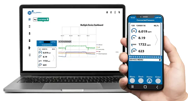
The Halogen D20 Display/Controller is a multi-channel device designed for use with the MP5 style chlorine analyzer and other Halogen Systems products. It provides real-time insights and intelligent analysis of onsite water quality.
Multiparameter Monitoring
Displays sensor readings and transmits analog/digital signals.
User-Friendly Interface
Easy configuration and calibration via the controller display.
Versatile Installation
Can be wall-mounted or pole-mounted.
Network Connectivity
Supports remote access for network-connected controllers.

Safety & Compliance Information
Important Safety Warnings:
Read this entire manual before unpacking, setting up, or operating the equipment.
Follow all danger and caution labels attached to the instrument.
This equipment is not intended for residential environments and may cause interference with radio reception.
Certifications & Compliance

NSF/ANSI/CAN 61 & 372 Certified (Safe for drinking water applications).
FCC Part 15, Class A Compliant (Tested for interference safety).
ETL Certified to UL and CSA safety standards.
Step-by-Step Installation Guide
01
Step
Planning & Required Tools
Before starting installation, confirm the following
Power availability (120VAC or 240VAC with conduit fittings).
Required tools:
#2 Phillips & Flathead screwdrivers.
Check the box contents
D20 Display/Controller
MP5 Sensor
Mounting tabs, cables, and installation guide
Mounting the D20 Display/Controller
You can mount the D20 Display/Controller in two ways
Wall Mounting
Attach the mounting tabs to the back of the enclosure.
Secure the D20 unit to the wall using the appropriate screws.
Pole Mounting
Secure the controller to a vertical or horizontal pole (0.75″–2.5″ diameter)
Ensure the unit is upright and level for best performance.
Ensure at least 6.3 inches of clearance for opening the display door.
02
Step
03
Step
Connecting Power & Wiring
Electrical Connections
120V/240V Power Input (Label A)
Alarm Output (2P conductor, optional)
Flow Sensor Input (5P conductor, optional)
MP5 Sensor Connection (M12 4P)
4-20mA Output for PLC connections
Wiring Diagram: See Page 7 of the manual for detailed pin connections.
Setting Up the MP5 Sensor
Install the MP5 Sensor into the flow cell.
Ensure the sensor outlet port is positioned vertically to purge air.
Connect the sensor using the M12 connector.
Limit inlet pressure to 60 PSI to prevent damage.
Reference Page 9 for detailed sensor installation instructions.
04
Step
05
Step
Startup & Commissioning
Power Up the D20
Plug in the power cable and ensure water is flowing.
Monitor Startup Status
The D20 screen will display status messages during boot-up.
Set Time & Communication Settings
Use the arrow keys to configure 4-20mA output scaling.